Um Tutorial sobre a Interface Porta Paralela

Fonte: A tutorial on Parallel port Interfacing

Introduction

Parallel port is a simple and inexpensive tool for building computer controlled devices and projects. The simplicity and ease of programming makes parallel port popular in electronics hobbyist world. The parallel port is often used in Computer controlled robots, Atmel/PIC programmers, home automation, ...etc... Here a simple tutorial on parallel port interfacing and programming with some examples.

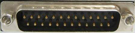
Everybody knows what is parallel port, where it can be found, and for what it is being used. the primary use of parallel port is to connect printers to computer and is specifically designed for this purpose. Thus it is often called as printer Port or Centronics port (this name came from a popular printer manufacturing company 'Centronics' who devised some standards for parallel port). You can see the parallel port connector in the rear panel of your PC. It is a 25 pin female (DB25) connector (to which printer is connected). On almost all the PCs only one parallel port is present, but you can add more by buying and inserting ISA/PCI parallel port cards.


Parallel port modes
The IEEE 1284 Standard which has been published in 1994 defines five modes of data transfer for parallel port. They are,

1) Compatibility Mode
2) Nibble Mode
3) Byte Mode
4) EPP
5) ECP

The programs, circuits and other information found in this tutorial are compatible to almost all types of parallel ports and can be used without any problems (Not tested, just because of confidence ! ). More information on parallel port operating modes can be found here.

Hardware
The pin outs of DB25 connector is shown in the picture below

Parallel Port

The lines in DB25 connector are divided in to three groups, they are

1) Data lines (data bus)
2) Control lines
3) Status lines

As the name refers , data is transferred over data lines , Control lines are used to control the peripheral and of course , the peripheral returns status signals back computer through Status lines. These lines are connected to Data, Control And Status registers internally . The details of parallel port signal lines are given below

Pin No (DB25)Signal nameDirectionRegister - bitInverted
1nStrobeOutControl-0Yes
2Data0In/OutData-0No
3Data1 In/Out Data-1 No
4Data2 In/Out Data-2 No
5Data3 In/Out Data-3 No
6Data4 In/Out Data-4 No
7Data5 In/Out Data-5 No
8Data6 In/Out Data-6 No
9Data7 In/Out Data-7 No
10nAck In Status-6 No
11Busy In Status-7 Yes
12Paper-Out In Status-5 No
13Select In Status-4 No
14Linefeed Out Control-1 Yes
15nError In Status-3 No
16nInitialize Out Control-2 No
17nSelect-Printer Out Control-3 Yes
18-25Ground - - -

Parallel port registers
As you know, the Data, Control and status lines are connected to there corresponding registers inside the computer. So by manipulating these registers in program , one can easily read or write to parallel port with programming languages like 'C' and BASIC.

The registers found in standard parallel port are ,

1) data register
2) Status register
3) Control register

As there names specifies, Data register is connected to Data lines, Control register is connected to control lines and Status register is connected to Status lines. (Here the word connection does not mean that there is some physical connection between data/control/status lines. The registers are virtually connected to the corresponding lines.). So what ever you write to these registers , will appear in corresponding lines as voltages, Of course, you can measure it with a multimeter. And What ever you give to Parallel port as voltages can be read from these registers(with some restrictions). For example , if we write '1' to Data register , the line Data0 will be driven to +5v. Just like this ,we can programmatically turn on and off any of the data lines and Control lines.

Where these registers are ?
In an IBM PC, these registers are IO mapped and will have unique address. We have to find these addresses to work with parallel port. For a typical PC , the base address of LPT1 is 0x378 and of LPT2 is 0x278. The data register resides at this base address , status register at baseaddress + 1 and the control register is at baseaddress + 2. So once we have the base address , we can calculate the address of each registers in this manner. The table below shows the register addresses of LPT1 and LPT2

RegisterLPT1LPT2
data registar(baseaddress + 0)0x3780x278
status register (baseaddress + 1)0x3790x279
control register (baseaddress + 2)0x37a0x27a

Programming Concepts
Almost all programming languages allow programmers to access parallel port using some library functions. For example , Borland C is providing "Inportb" and "Outportb" functions to read or write IO mapped peripherals. But the examples provided here in this tutorial is written VC++ and can be easily ported to other compilers like Borland C and Turbo C. Visual Basic does not have any functions or support to access parallel port directly, but it is possible to add such capabilities to your VB application by writing a dll in VC++ and calling its exported functions from VB. VC++ provides two functions to access IO mapped peripherals, '_inp' for reading and '_outp' for writing. These functions are declared in "conio.h".

Hardware for testing sample programs
The schematic diagram of the test circuit is shown below. It is recommended to build this circuit before testing the sample programs

Test hardware

Sample program in VC++

Writing a parallel port interfacing program in VC++ is very easy. Here is the steps to write your first parallel port interfacing application in VC++.

Start VC++ IDE , Select 'New' from File menu.Then select “Win32 Console Application” from “Projects” tab(picture-3). enter project name as “partest1” , then click OK button.

Picture3

Picture-3

Now you can see a dialog box with caption “Win32 Console Application - step 1 of 1” (picture-4).

Picture 4

Picture-4

Select “a simple Application” and click Finish. Now open example1.cpp from “fileview” and replace the existing code with the code given below.


#include "stdafx.h"
#include "conio.h"
#include "stdio.h"
#include "string.h"
#include "stdlib.h"

int main(int argc, char* argv[])
{
short data;

if(argc<2)
{
printf("Usage\n\n");
printf("partest1.exe ,,\n\n\n");
return 0;
}

if(!strcmp(argv[1],"read"))
{
data = _inp(atoi(argv[2]));
printf("Data read from parallel port is ");
printf("%d\n\n\n\n",data);
}

if(!strcmp(argv[1],"write"))
{
_outp(atoi(argv[2]),atoi(argv[3]));
printf("Data written to parallel port is ");
printf("%s\n\n\n\n\n",argv[3]);
}
return 0;
}

Build the project and copy partest1.exe to "c:\".

How to Test The Program ?

Connect The assembled hardware shown above to your PC's parallel port. Open DOS command window Move to "C:\" and type "partest1 write 888 255" and press enter. If everything is correct , LED1 to LED8 in the hardware will glow. You may be doubtful about the command line parameters passed to the program. Here 888(0x378) is the address of the parallel port data register and 255 is the data to be written to parallel port data register. if you enter "partest1 read 888" to command line , the program will read parallel port data register and display it. This will blindly read the contents of parallel port data register , but not the data present on data lines. To read the data from the data lines , we will have to enable the bidirectional data transfer first. To enable Bidirectional data transfer just set the "Bidirectional" bit (bit 5) in control register. This is done by writing 32 to control register. The command "partest1 write 890 32" will do this. After entering this command you can read the status of switches in the hardware using the command "partest1 read 888"

NOTE: This sample program will not work on Windows NT/2000 or XP if you run the program on these machines , it will show an error. use new Inpout32.dll on NT/2000/XP machines

Como a Biblioteca INPOUT32.DLL funciona?

Fonte: Logix4u

Tried the Inpout32.dll..? then Learn how Inpout32.dll does the things. This brief tutorial explains about the working of Inpout32.dll in simple steps, with the help of a flow chart. This could help you much if you want to modify the Inpout32 dll source code

If you don't know what is Inpout32.dll, please read it here and then continue.

How it works

The outstanding feature of Inpout32.dll is , it can work with all the windows versions without any modification in user code or the DLL itself. This tutorial describes how it is achieved, what programming methods used, what are the APIs used, etc.... The Dll will check the operating system version when functions are called, and if the operating system is WIN9X, the DLL will use _inp() and _outp functions for reading/writing the parallel port. On the other hand, if the operating system is WIN NT, 2000 or XP, it will install a kernel mode driver and talk to parallel port through that driver. The user code will not be aware of the OS version on which it is running. This DLL can be used in WIN NT clone operating systems as if it is WIN9X. The flow chart of the program is given below.

The two important building blocks of this program are

1) A kernel mode device driver embedded in the DLL in binary form

2) The DLL itself

Kernel mode driver Hwinterface.sys

The source code of Hwinterface.sys kernel mode driver is located in "kernel_mode_driver_source" directory. Where "hwinterfacedrv.c" is the main application source file. Three functions implemented in the driver are

1) DriverEntry() , Called when driver is loaded. Creates device object and symbolic links.

2) hwinterfaceUnload(), Called when driver is unloaded, performs clean up

3) hwinterfaceDeviceControl(), handles calls made through DeviceIOControl API. Performs reading writing to the parallel port according to the control code passed.

The DLL Inpout32

The functions in the DLL are implemented in two source files, "inpout32drv.cpp" and "osversion.cpp". osversion.cpp checks the version of operating system. "inpout32drv.cpp" does installing the kernel mode driver, loading it , writing/ reading parallel port etc... The two functions exported from inpout32.dll are

1) Inp32(), reads data from a specified parallel port register.

2) Out32(), writes data to specified parallel port register.

the other functions implemented in Inpout32.dll are

1) DllMain(), called when dll is loaded or unloaded. When the dll is loaded , it checks the OS version and loads hwinterface.sys if needed.

2) Closedriver(), close the opened driver handle. called before unloading the driver.

3) Opendriver(), open a handle to hwinterface driver.

4) inst() , Extract 'hwinterface.sys' from binary resource to 'systemroot\drivers' directory and creates a service. This function is called when 'Opendriver' function fails to open a valid handle to 'hwinterface' service.

5) start() , starts the hwinterface service using Service Control Manager APIs.

6) SystemVersion() Checks the OS version and returns appropriate code.

What is hwinterface.ocx ActiveX control

It is an activex control with same features of Inpout32.dll. It can be used either with VC++ or VB. But it gives great convenience when used with VB. Data can be written to parallel port using Outport method and can be read using Inport method.

Download Inpout32.dll and source code here


Useful links

Windows NT/Windows 2000/WDM Driver FAQ by Jamie E. Hanrahan

Programming Windows Driver Model by Walter Oney

Details of all the APIs used is available at MSDN Online

Sobre INPOU32.DLL for Windows 98/2000/NT/XP

Fonte: http://www.lvr.com/, Logix4u

The Problem

Writing programs to talk with parallel port was pretty easy in old DOS days and in Win95/98 too. We could use Inporb and outportb or _inp() or _Outp functions in our program without any problem if we are running the program on DOS or WIN95/98. But entering to the new era of NT clone operating systems like WIN NT4, WIN2000, WINXP, all this simplicity goes away. Being interested in Parallel port interfacing and programming you might have experienced the problems in writing a program that can talk to parallel port successfully in NT based operating systems. When we are trying to run a program which is written using the conventional software functions like Inporb, outportb, _inp() or _Outp on a WINNT or WIN2000 system, it will show an error message that "The exception privileged instruction occurred in the application at location ....". The picture of such a messagebox is given at Logix4u.

Staring to this messagebox, you might have been thinking.... "did i make a mistake in my program ?" it is working fine on WIN98 ... Who is guilty here. 'Nobody' that is the answer. Then why it is happening like this ..? The answer is in the next paragraph

Being a very secure operating system, Windows NT assigns some privileges and restrictions to different types of programs running on it.It classifies all the programs in to two categories , User mode and Kernel mode ie; running in ring3 and ring0 modes. user mode programs are running in ring3 mode and Kernel mode programs are running in ring0 mode. The programs you generally write falls in the user mode category. The user mode programs are restricted to use certain instructions like IN, OUT etc.. Whenever the operating system find that a user mode program is trying to execute such instructions , the operating system stops execution of those programs and will display an error message. Eventually our interfacing programs stops where they are executing IN or OUT instructions to read or write data to parallel port. But in the same time Kernel mode programs are in no way restricted in executing such instructions. Device drivers are capable of running in kernel mode. So the work around for the above stated problem is to write a kernel mode driver capable of reading and writing data to parallel port and let the user mode program to communicate with it. Writing a driver is not an easy job for even experienced programmers. But writing a simple driver for communicating with parallel port is a simple task when drivers like USB, sound card etc.. are concerned. Even though you get a working driver from somewhere else, installing and configuring it can be very cumbersome task.

The Solution

Introducing Inpout32.dll for WIN 98/NT/2000/XP. This dll have the following features

  1. Works seam less with all versions of windows (WIN 98, NT, 200 and XP)
  2. Using a kernel mode driver embedded in the dll
  3. No special software or driver installation required
  4. Driver will be automatically installed and configured automatically when the dll is loaded
  5. No special APIs required only two functions Inp32 and Out32
  6. Can be easily used with VC++ and VB
  7. Functions are compatible with Jan Axelsons Inpout32.dll (available at http://www.lvr.com/parport.htm). So this dll can be used with the sample programs available with the book Parallel Port Complete, without any modification.

Click here for a sample program written for Borland C++ command line compiler, by Douglas Beattie Jr.

Click here for a sample program written for Real Basic, by Aaron Ballman.

Click here for 64 bit version of inpout which can be used with 64 bit windows, by Phil.

Examplo de Interface LCD de 16 Character x 2 Lines

Fonte: Beyondlogic.org

/*  LCD Module Software                                               */
/* 17th May 1997 */
/* Copyright 1997 Craig Peacock */
/* WWW - http://www.senet.com.au/~cpeacock */
/* Email - cpeacock@senet.com.au */
/* */
/* Register Select must be connected to Select Printer (PIN 17) */
/* Enable must be connected to Strobe (PIN1) */
/* DATA 0:7 Connected to DATA 0:7 */

#include
#include

#define PORTADDRESS 0x378 /* Enter Your Port Address Here */

#define DATA PORTADDRESS+0
#define STATUS PORTADDRESS+1
#define CONTROL PORTADDRESS+2

void main(void)
{
char string[] = {"Testing 1,2,3 "
"It' Works ! "};
char init[10];
int count;
int len;
init[0] = 0x0F; /* Init Display */
init[1] = 0x01; /* Clear Display */
init[2] = 0x38; /* Dual Line / 8 Bits */

outportb(CONTROL, inportb(CONTROL) & 0xDF); /* Reset Control Port - Make sure Forward Direction */

outportb(CONTROL, inportb(CONTROL) 0x08); /* Set Select Printer (Register Select) */

for (count = 0; count <= 2; count++)
{
outportb(DATA, init[count]);
outportb(CONTROL,inportb(CONTROL) 0x01); /* Set Strobe (Enable)*/
delay(20); /* Larger Delay for INIT */
outportb(CONTROL,inportb(CONTROL) & 0xFE); /* Reset Strobe (Enable)*/
delay(20); /* Larger Delay for INIT */
}

outportb(CONTROL, inportb(CONTROL) & 0xF7); /* Reset Select Printer (Register Select) */

len = strlen(string);

for (count = 0; count < len; count++)
{
outportb(DATA, string[count]);
outportb(CONTROL,inportb(CONTROL) 0x01); /* Set Strobe */
delay(2);
outportb(CONTROL,inportb(CONTROL) & 0xFE); /* Reset Strobe */
delay(2);
}
}

Programando Módulo de LCD via Porta Paralela

Fonte: ElectroSofts

#include "dos.h"
#include "string.h"
#include "conio.h"
#include "time.h"


#define PORTADDRESS 0x378 /* Enter Your Port Address Here */

#define DATA PORTADDRESS+0
#define STATUS PORTADDRESS+1
#define CONTROL PORTADDRESS+2

void lcd_init(void);
void lcd_write(char char2write);
void lcd_putch(char char2write);
void lcd_puts(char * str2write);
void lcd_goto(int row, int column);
void lcd_clear(void);
void lcd_home(void);
void lcd_cursor(int cursor);
void lcd_entry_mode(int mode);


void main(void)
{

lcd_init();
lcd_goto(1,1);
lcd_puts("Welcome To");
lcd_goto(1,0);
lcd_puts("electroSofts.com");

while(!kbhit() ) //wait until a key is pressed...
{}

}

void lcd_init()
{

outportb(CONTROL, inportb(CONTROL) & 0xDF);
//config data pins as output

outportb(CONTROL, inportb(CONTROL) 0x08);
//RS is made high: control (register select)

lcd_write(0x0f);
delay(20);
lcd_write( 0x01);
delay(20);
lcd_write( 0x38);
delay(20);

}

void lcd_write(char char2write)
{

outportb(DATA, char2write);
outportb(CONTROL,inportb(CONTROL) 0x01); /* Set Strobe */
delay(2);
outportb(CONTROL,inportb(CONTROL) & 0xFE); /* Reset Strobe */
delay(2);

}

void lcd_putch(char char2write)
{

outportb(CONTROL, inportb(CONTROL) & 0xF7);
//RS=low: data
lcd_write(char2write);

}

void lcd_puts(char *str2write)
{

outportb(CONTROL, inportb(CONTROL) & 0xF7);
//RS=low: data
while(*str2write)
lcd_write(*(str2write++));

}

void lcd_goto(int row, int column)
{

outportb(CONTROL, inportb(CONTROL) 0x08);
if(row==2) column+=0x40;
/* Add these if you are using LCD module with 4 columns
if(row==2) column+=0x14;
if(row==3) column+=0x54;
*/

lcd_write(0x80 column);

}

void lcd_clear()
{

outportb(CONTROL, inportb(CONTROL) 0x08);
lcd_write(0x01);

}

void lcd_home()
{

outportb(CONTROL, inportb(CONTROL) 0x08);
lcd_write(0x02);

}

void lcd_entry_mode(int mode)
{

/*
if you dont call this function, entry mode sets to 2 by default.
mode: 0 - cursor left shift, no text shift
1 - no cursor shift, text right shift
2 - cursor right shift, no text shift
3 - no cursor shift, text left shift
*/

outportb(CONTROL, inportb(CONTROL) 0x08);
lcd_write(0x04 + (mode%4));

}

void lcd_cursor(int cursor)
{

/*
set cursor: 0 - no cursor, no blink
1 - only blink, no cursor
2 - only cursor, no blink
3 - both cursor and blink
*/


outportb( CONTROL, inportb(CONTROL) 0x08 );
lcd_write( 0x0c + (cursor%4));

}

Exemplo de Programa para Escrever no Módulo LCD

void main(void)
{

struct time t;
struct date d;
char strtime[17];

textbackground(0);
clrscr();
textcolor(0);
textbackground(10);
gotoxy(8,5);
cputs(" ");
gotoxy(8,4);
cputs(" ");

lcd_init();
lcd_cursor(0);

while(!kbhit())
{

gettime(&t);
getdate(&d);
lcd_goto(0,4);
sprintf(strtime,"%02d:%02d:%02d", t.ti_hour%12, t.ti_min, t.ti_sec);
lcd_puts(strtime);
gotoxy(12,4);
cputs(strtime);

lcd_goto(1,3);
sprintf(strtime,"%02d:%02d:%4d", d.da_day, d.da_mon, d.da_year);
lcd_puts(strtime);
gotoxy(11,5);
cputs(strtime);
delay(200);

}
textbackground(0);
textcolor(7);

}

Programando a Porta Paralela

Interfacing to the IBM-PC Parallel Printer Port
Interfacing the Standard Parallel Port (parallel.pdf)
Parallel Port Programming Tutorial (http://electrosofts.com/parallel/)
Parallel Port Programming (PART 1): with C

Porta Paralela do PC (DB-25 Fêmea)

Fonte: Pinouts

25 pin D-SUB female connector layoutPhoto view of 25 pin D-SUB female connector

Parallel port will allow the input of up to 9 bits or the output of 12 bits at any one given time. This port may be used for interfacing home made projects since external circuitry is minimal for many simple tasks. The port is composed of 4 control lines, 5 status lines and 8 data lines. It's found commonly on the back of your PC as a 25 Pin D-SUB female connector (note, that 25 pin D-SUB male connector represent RS-232 serial port, not compatible with LPT!).

There are differnt modes of Parallel port work in modern computer. Take a look to newer ECP Parallel LPT port (IEEE-1284A) interface for more detailed explanations. Information included in current page is about older, but still widely accepted SPP LPT port interface. ECP specification includes SPP as one of possible modes.

Pin Name Dir Description

1

/STROBE

-->

Strobe

2

D0

-->

Data Bit 0

3

D1

-->

Data Bit 1

4

D2

-->

Data Bit 2

5

D3

-->

Data Bit 3

6

D4

-->

Data Bit 4

7

D5

-->

Data Bit 5

8

D6

-->

Data Bit 6

9

D7

-->

Data Bit 7

10

/ACK

<--

Acknowledge (bit D6)

11

BUSY

<--

Busy (bit ~D7)

12

PE

<--

Paper End (bit D5)

13

SEL

<--

Select (bit D4)

14

/AUTOFD

-->

Autofeed

15

/ERROR

<--

Error (bit D3)

16

/INIT

-->

Initialize

17

/SELIN

-->

Select In

18

GND

--

Signal Ground

19

GND

--

Signal Ground

20

GND

--

Signal Ground

21

GND

--

Signal Ground

22

GND

--

Signal Ground

23

GND

--

Signal Ground

24

GND

--

Signal Ground

25

GND

--

Signal Ground

The data output of the Parallel Port is normally TTL logic levels. Most Parallel Ports implemented in ASIC, can sink and source around 12mA. However voer variations possible: Sink/Source 6mA, Source 12mA/Sink 20mA, Sink 16mA/Source 4mA, Sink/Source 12mA and others.

Centronics is an early used standard for transferring data from a host to the printer. The majority of printers use this handshake.

               ______          ___________________
nStrobe \ /
\______/
______________
Busy / \
______/ \___________
______________________ ____
nAck \ /
\_____/
___ _______ _________________
\ / \ /
Data \/ \/
/\ /\
__ / \_______/ \_________________

Data is first applied on the Parallel Port pins 2 to 7. The host then checks to see if the printer is busy. i.e. the busy line should be low. The program then asserts the strobe, waits a minimum of 1mS, and then de-asserts the strobe. Data is normally read by the printer/peripheral on the rising edge of the strobe. The printer will indicate that it is busy processing data via the Busy line. Once the printer has accepted data, it will acknowledge the byte by a negative pulse about 5mS on the nAck line. Host may ignore the nAck line to save time.

Note: Direction is Computer relative Device.


Pinagem do IEEE-1284-A (DB-25)

Fonte: Pinout

Nomes dos Sinais IEEE-1284-B

Fonte: Pinout

25-DSub 36-Cen
Strobe11
Data Bit 022
Data Bit 133
Data Bit 244
Data Bit 355
Data Bit 466
Data Bit 577
Data Bit 688
Data Bit 799
Acknowledge1010
Busy1111
Paper Out1212
Select1313
Autofeed1414
Error1532
Reset1631
Select1736
Signal Ground1833
Signal Ground1919,20
Signal Ground2021,22
Signal Ground2123,24
Signal Ground2225,26
Signal Ground2327
Signal Ground2428,29
Signal Ground2530,16
ShieldShieldShield+17

Pinagem do IEEE-1284-B (36-Centronics)

Fonte: Pinout

36 pin CENTRONICS female connector layout

PinSignalAbbr.Source
1Data Strobe (low)STROBEComputer
2Data Bit 1 (LSB)D1Computer
3Data Bit 2D2Computer
4Data Bit 3D3Computer
5Data Bit 4D4Computer
6Data Bit 5D5Computer
7Data Bit 6D6Computer
8Data Bit 7D7Computer
9Data Bit 8 (LSB)D8Computer
10Acknowledge (low)ACKPrinter
11Busy (high)BUSYPrinter
12Paper End (high)PEPrinter
13Select (high)SELPrinter
14Supply Ground-
15Oscillator TransmitPrinter
16Logical Ground-
17Chassis Ground-
18+5 Vdc+VPrinter
19Return Data Strobe-
20Return Data Bit 1-
21Return Data Bit 2-
22Return Data Bit 3-
23Return Data Bit 4-
24Return Data Bit 5-
25Return Data Bit 6-
26Return Data Bit 7-
27Return Data Bit 8-
28Return ACK-
29Return BUSY-
30Return Input Prime-
31Input Prime (low)Computer
32Fault (low)FAULTPrinter
33---
34---
35---
36---

Cabo para Impressora Paralela: Pinagem e Conectores

Fonte: Pinout

25 pin D-SUB male connector layout
36 pin CENTRONICS male connector diagramPhoto view of 36 pin CENTRONICS male connector
25-DSub 36-Cen
Strobe11
Data Bit 022
Data Bit 133
Data Bit 244
Data Bit 355
Data Bit 466
Data Bit 577
Data Bit 688
Data Bit 799
Acknowledge1010
Busy1111
Paper Out1212
Select1313
Autofeed1414
Error1532
Reset1631
Select1736
Signal Ground1833
Signal Ground1919,20
Signal Ground2021,22
Signal Ground2123,24
Signal Ground2225,26
Signal Ground2327
Signal Ground2428,29
Signal Ground2530,16
ShieldShieldShield+17


Introdução ao Padrão IEEE-1284-B

Fonte: IEEE 1284 (Wikipedia), Pinout

IEEE-1284 (officially known as 1284-1994, Standard Signaling Method for a Bidirectional Parallel Peripheral Interface for PCs) refers to a standard set by the Institute of Electrical and Electronic Engineers. It specifies, among other things, five modes of data transfer: standard (legacy style), reverse (nibble and byte modes), and half-duplex or bidirectional (EPP and ECP). It also details cable properties and connector types. The 1284 standard is an innovation that allows parallel printer ports to transfer data at many times the standard speed, and also allows for an array of bidirectional communications and longer cable runs. The Enhanced Parallel Port (EPP) and Extended Capabilities Port (ECP) both follow 1284 standards, although EPP was developed prior to 1284"s release. The primary advantage of this technology is the ability to use devices on a PC"s parallel port that were previously unable to be used because of communication limitations. However, printers have also benefited and Hewlett-Packard"s Bitronix protocol, introduced with their LasetJet 4, is proof. Bitronix takes advantage of 1284"s nibble mode, and allows data to be sent from the printer to the computer quickly in this manner.

What is the difference between an IEEE-1284 cable and a standard one?

This is often a misunderstood concept. First, let"s make the distinction between bidirectional and 1284-compliant cables. Applying the 1284 standard to cables, the IEEE-compliance primarily means speed, and these cables are precisely manufactured for that purpose. The 1284 standard sets exacting specifications on cable impedance, shielding, length, and connector styles to insure that they will be up to the task. Bidirectional cables must simply be able to transfer data in both directions, and your everyday 25-wire printer cables (and all straight-thru 25 wire cables) are capable of this; they are not, however, capable of the speed required by 1284-compliant peripherals. Peripherals which are IEEE-1284 compliant (such as many newer printers) require the use of a high-speed cable, as do most of the devices that connect to an EPP or ECP.

Describe the connectors that are used on these cables.
There are three official types of connectors: they are termed "A," "B," and "C." The "A" type is a standard DB25 and the "B" type is your typical Centronics 36 connector. The "C" type is exclusive to 1284, and is intended to be used on new equipment which conforms to the standard; it is called a half-pitch Centronics 36 connector (HPCN36).

What devices require IEEE-1284 cables?

As a rule of thumb, any device that requires your computer"s parallel port to be set to EPP/ECP mode is worthy of a 1284-compliant cable. Specifically, most newer printers, backup devices, scanners, and the like require these cables. In addition, any parallel device with an HPCN36 connector requires a 1284 cable. If in question, refer to the user"s manual of that specific device.

Can I use a non-1284 compliant cable instead of one that is?

It is possible, but not recommended. Results can range from limited success to complete lack of operation.

What are the length restrictions on cables? Do I need to terminate the end of the chain?

In order to maintain peak performance, the total distance from computer to the last device should be no more than about 35 feet. Longer runs may be utilized with a possible drop in overall performance. No external termination is required; peripherals already come with the necessary termination. At PC Cables and Parts, you"ll discover an easy to use, information packed web site. Click here to learn more about Printer Cables.

Note: Direction is Computer relative Device.

Conectores 36-pinos Centronics

Fonte: Wikipedia, Amphenol, Micro Ribbon

36 pin CENTRONICS female connector
36 pin CENTRONICS male connector